Control Systems Group Robotics Lab
Hexapod Robot Project
Bruce B. Abbott, Ph.D.
Project Director
Overview
The goal of the hexapod robot project is to provide a physical test-bed for developing and testing control-system architectures conforming to the principles of Perceptual Control Theory (Powers, 1973). The hexapod design was selected for this project because hexapods do not require complex balancing mechanisms (thus simplifying design requirements), and because it will allow me to take advantage of Richard Kennaway's hexapod computer simulation's control mechanisms.
General Design requirements include the following:
- Low cost -- the entire system must be produced within the constraints of a very modest budget.
- Relative simplicity -- it must be within my technical competence to build and program.
With these considerations in mind, I have spent the past week or so researching components. At present, the following arrangement looks attractive to me:
- General construction
I will probably construct the body and legs of the robot from high-grade, 1/8" thick multi-ply SIG plywood. This is a relatively strong but light-weight material that can be easily cut into complex shapes and glued to form strong three-dimensional structures as in R/C model aircraft.
- Legs
In the initial design I intend to use R/C servos (as found in model aircraft, boats, and cars), three to each leg, to provide the motive power. One servo will provide front/back movement at the "hip," one will lift the leg at the "hip," and one will actuate the knee joint. Each leg will be equipped with sensors to register contact of the "foot" with the ground and contact of the leg with obstacles.
- Leg controllers
Each leg (or possibly each pair of legs) will have its own dedicated micro-controller that will operate the servos, receive feedback from the leg sensors, and implement bottom-level control systems.
- Higher-level controllers
Further details of the "nervous system" will have to be worked out on the basis of experiment. Low-level perceptual references may be fed directly into a PC where all higher-level control systems reside. Alternatively, there may be further on-board controllers to handle local control at the next level(s). These controllers will communicate with each other and with other sensory devices (e.g., a sonar range-finder) via a local bus (most likely the I2C bus).
- Higher-level sensory input
The hobby market is beginning to provide relatively low-cost sensory systems that can be tied to the controllers in a fairly simple way. These include (among others) a two-axis inclinometer for measuring body tilt, a magnetic compass to give heading information, sonar and infrared rangefinders for measuring distance to objects, and a pryoelectric sensor capable of detecting the heat of a human or animal body. At some point we will probably want to install one or more of these to provide additional high-level perceptual control capabilities, so that our "insect" can find its way about without running into things and demonstrate other simple behaviors such as phototaxis.
Initial Status
The first step is to investigate the options provided by various commercially-available controller boards designed specifically for the hobbiest robotics market. I have completed a web search that identified several promising boards. These generally come with on-board circuits for A/D conversion (to get analog sensory signals into digital format within the controller), I/O pins capable of driving the R/C servo motors, a communications bus to allow data to be exchanged between controller boards, sensors, and PC, and a local eeprom memory that can receive and hold instructions and data needed to implement local control algorithms. An important consideration is ease of programming. Some of these boards come with high-level compiler software that allow one to write the control routines in languages compatible with BASIC, Visual BASIC, C, or JAVA; these are compiled and the result sent to the local controller's eeprom where it can be executed without further need for the PC. I've also consulted with two of our Electrical Engineering Technology (EET) professors about which packages might be best for this application.
After giving the options careful consideration, I have decided to order an OOPic II Controller Starter Package ($69) and will be conducting tests with it to determine the OOPic II's suitability for use as a servo controller and as a higher-level controller. I already own a small number of R/C servos to use for these tests, but will order different ones specifially for the project if the tests prove successful. The OOPic is capable of driving up to 21 servos but timing and memory demands would probably be too extreme for our purposes with that many, so I will be investigating how well the controller can work with either three (one leg) or six (two legs).
Progress Reports
Here is where you will find periodic progress reports documenting what is being done.
10 April 2002
Thus far no money has been spent, but Bill Powers and I have been considering possible designs for a first-order control system, using an R/C servo, that would behave like the muscle-system in a real organism. It would include sensors for "muscle" length and force, and a rate-based damping circuit that eliminates the need for a physical dashpot. I breadboarded and tested an initial circuit for this that Bill designed, but investigation of the way the reference position of an R/C servo is set suggests that the circuit will have to be modified to comply with the servo's encoding method.
Meanwhile I've been receiving assistance from one of our Psychology students, Stephen O'Shaughnessy, who has a degree in EET and programs computers for a living. He's worked up a preliminary drawing of the servo/controller circuit arrangement in PowerPoint format and has begun to read B:CP. He's also looking into the problem of programming the communication between our on-board processors via the I2C bus.
Recently I've been spending time reading a couple of Rodney Brooks' books in which he describes his "subsumption" approach to robotics. This resembles PCT somewhat in that it is a bottom-up approach, but there are significant differences and it will be interesting to compare our design's abilities to those achieved by the subsumption-based machines.
2 July 2002
Quite a number of things have happened since the previous report on 10 April. These include the following:
- An OOPic II controller (from Savage Innovations) was purchased for evaluation. The OOPic II includes 31 I/O lines, four 8-bit A-to-D converters, and can communicate with other OOPICs or devices via an "I2C" bus. A major attraction is that its programs can be written on a PC and then downloaded into the OOPic's EEPROM memory without the need for special devices. In addition, it can be programmed in a high-level object-oriented language that includes a number of predefined objects that communicate directly with hardware such as R/C servos.
- Two sizes of R/C (radio control) servos (used in radio-controlled model cars, boats, and aircraft) were purchased to evaluate their suitability for the project. These include the HiTec HS-645MG high-torque standard-size servo and the HiTec HS-225MG high-torque mini-servo. (In both cases the "MG" stands for "metal gear.")
- The OOPic was programmed to set the reference position of one of the servos, alternating back and forth between two positions (with suitable delays between movements). This demonstrated that (a) the OOPic works, (b) I had the servo connected correctly to the OOPic, (c) I can write an OOPic program that does what I intended it to do, and (d) the programming link from my PC to the OOPic works properly.
- A conductive rubber pad was ordered and received. This is a pressure-sensitive material whose electrical resistance decreases from about 2 meg Ohms to nearly 0 Ohms as the pressure exerted on the pad increases. This material may provide the basis for the force sensors at the joints and foot-pads.
- A prototype leg (upper and lower leg segments only) was constructed that included one servo to operate the knee joint via a chain-and-sprocket arrangement. This prototype also tested a piano-wire spring system intended to give the leg "muscle" a degree of stretch similar to that of real muscle. (The knee-joint's angle could differ somewhat from the angle dictated by the servo's angular output position due to the bending of the wire.) Tests under load revealed that the spring system worked as expected but that the plastic sprocket chain stretched too much.
- Tests using the OOPic to set the servo references revealed that the angular resolution of the reference positions was inadequate for our purpose. The OOPic's built-in servo object uses a number between 0 and 127 to set the servo's reference position. As the number of degrees that the servo can turn is a bit over 180, this yielded an angular resolution of approximately 1.5 degrees per step.
- Further investigation revealed that the OOPic's programming language includes another servo object designed to interface with something called the "Scott Edwards mini-ssc," where "ssc" turns out to stand for "serial servo controller." This board is capable of driving up to eight servos and uses only one I/O line (plus ground) to connect to the OOPic. Better yet, it can deliver an angular resolution of 0.72 degrees in 180-degree mode and has a 90-degree mode with a resolution of 0.36 degrees.
- A Scott Edwards mini-scc was purchased and tested. It receives servo positioning commands (references) via a standard serial port such as found on most PCs or it can be connected via the serial port to the OOPic controller. Positioning a servo then amounts to sending the controller a series of three 8-bit bytes: 255, followed by the servo number (0 to 7), followed by the reference position for that servo. A nice thing about this arrangement is that it takes away from the OOPic the responsibility for generating the pulse-width modulated signals required by the servos, freeing the OOPic to do other things. In addition, only one OOPic line can be used to drive up to 16 servos (via two mini-sscs), freeing up I/O lines on the OPic for receiving inputs from sensors. In addition, the mini-ssc can be connected directly to the PC via a serial line, allowing servos, legs, etc. to be tested, control algorithms developed, and so on from the PC directly, rather than having to write and download programs for the OOPic.
- Steven O'Shaughessey purchased an OOPic of his own and has been learning how to use the OOPic's I2C bus to create a network over which OOPics can communicate with each other and with I2 C devices such as the digital compass. This is important as the hexapod will probably have two or more OOPics plus some of these other devices, and we'll need to get them all to talk to one another.
- A second leg was built (upper and lower segment plus hip and knee-joints) to evaluate the lifting power of the servos, given the leg geometry I thought might be appropriate. This version uses the servo output wheels as the joints and thus lacks the spring system of the first prototype. Testing involved writing a program in Delphi that allowed me to adjust the joint-angles by using the PC's mouse to adjust two "slider" controls on the PC's screen, the servos being connected to the PC via the serial port to the mini-ssc. The "hip" (actually the body of the hip-joint servo) was clamped in place and an Ohaus pan balance moved into position so that the tip of the "foot" rested near the center of the pan. Readings from the scale were taken (in grams) as the servo position reference was changed so as to drive the leg down against the pan. Testing indicated that the leg could support the anticipated load so long as the hexapod doesn't get heavier than I anticipate it will.
- Not yet ready but in preparation is a test of the conductive rubber mat using the OOPic and the second leg. I plan sandwich a bit of the mat between two conductors and have the tip of the lower leg-segment ("foot") press against the top conductor. I want to know whether I can establish reasonable control over the pressure exerted against the pad by the "foot."
14 August 2002
The second leg demo, described immediately above, was shown off at the 2002 CSG conference and Bill Powers and I did a bit of playing around with a Delphi program that operated the leg through the RS-232 interface to Bill's laptop.
|
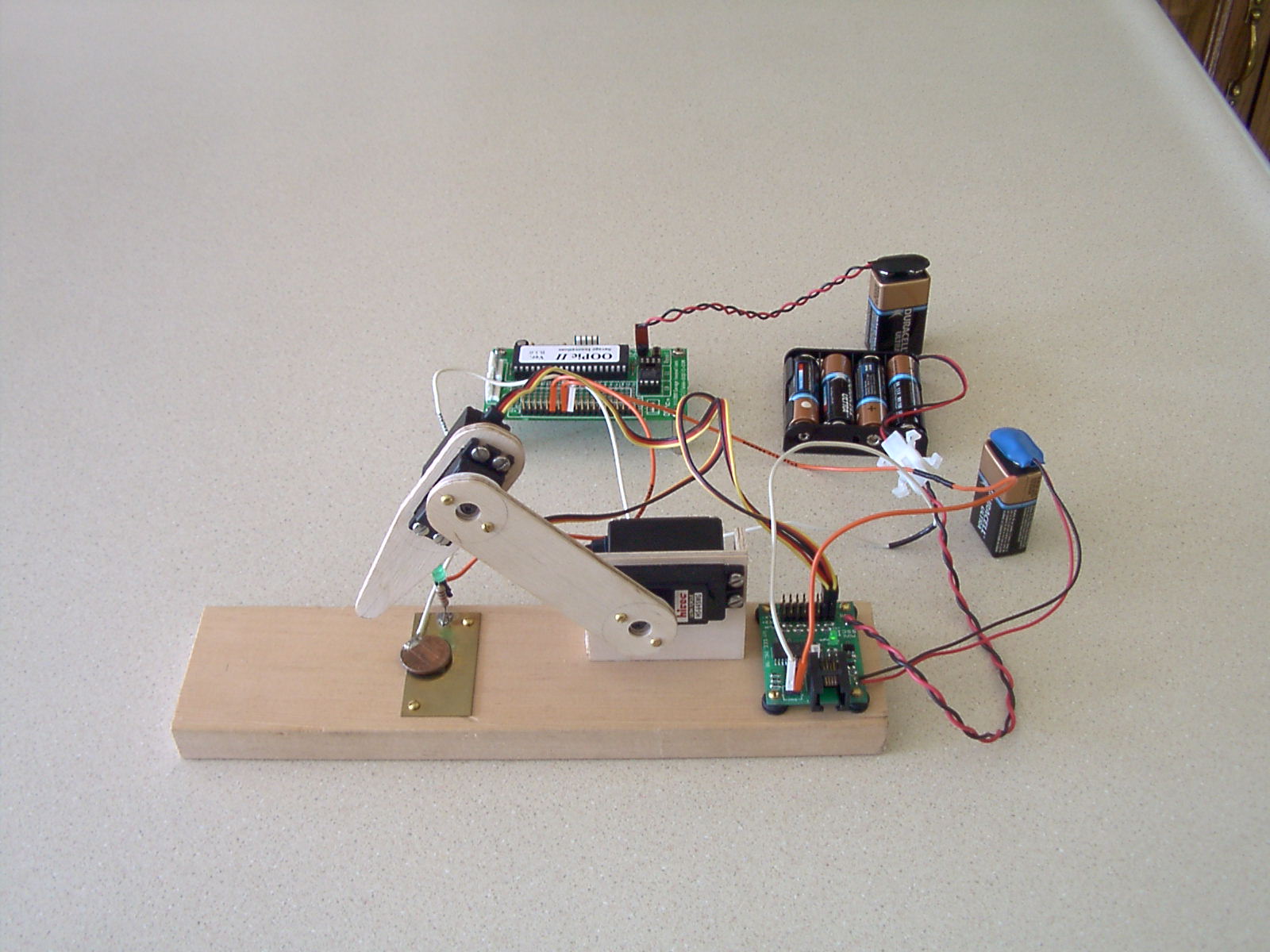
If your browser supports embedded movies, you should see a short continuous-loop movie showing a complete cycle of the leg (otherwise you will see a still photo). When the leg comes down on the coin immediately below it, note how the LED at the back edge of the brass strip lights up. Sandwiched between the coin and brass strip is a small square of conductive rubber pad, whose electrical resistance decreases with increasing applied pressure. The material is being evaluated as a possible element for Thoat's force sensors.
Also seen in the picture are the OOPic II controller (behind the leg) and the Scott Edwards serial servo controller board (mounted on the leg stand), as well as the batteries powering the system.
|
Related Sites
Under construction, but this is the place to find links to other robotics labs doing similar work.